Showing posts with label Vogel. Show all posts

Thursday, February 25, 2016

B2 - Dianna Vogel: Reflection Post

Overall I believe AE510 was a useful and interesting course to take. Obviously, as a structural engineering major I got more out of the first half of the class compared to the second half. This was due to the prevalence of Revit in the workforce and my desire to learn more in order to enhance my future. This class did indeed help me learn more about Revit. This was accomplished through the Revit family project, and my group project. For my group project we are creating the Farnsworth House in Revit, with all the components. This includes the architectural side, structural, and MEP. The Revit family assignment even assisted with the group project by opening a door I did not know existed. Prior to this class I did not realize that families could be created from scratch in Revit. This is a very beneficial tool in case a certain family object already existing in Revit cannot be altered to fit the projects purpose. While this information was helpful for our project, I thoroughly believe it will come in handy in the future. There may be a building in my future job that has to be created in Revit, and families need to be designed due to the objects being unique in some way.

Another important and helpful part of this class were the guest speakers. They gave insight into the different parts of the current workforce and how they have handled the problems presented to them. Furthermore, the most interesting topic I learned from multiple of the presenters was the job of seeing what clashes exist between different portions of a job, and how to deal with them. I did not realize this was a technique that is currently used by firms, even though it makes a lot of sense. The program that most of the used was Navisworks by Autodesk. I am hoping that my group has time to use this program to see what clashes may exist between our structural and MEP model, but that is dependent on how fast the MEP model is completed.

One effect of the course was forcing me to learn the basics of databases. This was a skill I would have never done willingly, but I do believe it is useful. I now know the basics of how to use access to create tables, queries, and forms. Therefore, if in the future it would be beneficial for a database to be created at my job, or in my school career, I at least know how to get started. Thus, I have gained many different types of useful information from AE510 and would highly suggest it to anyone in the future.

Comments:

http://ae-510-ay15-16.blogspot.com/2016/02/b6-group-b-alex-palma.html
Alex,
I definitely agree with what you said about learning from the speakers what you do not want to do in life. Sometimes this is more helpful than hearing someone speak on a topic you are interested in, depending on the length of time. With this extra knowledge, if down the road you are offered a job performing a task that you know you DON’T like then the job can be altered. However, if you have never heard of a specific job, or task, then it won’t be clear if you like or dislike it and may be stuck doing something unpleasant. Likewise, I fully agree that AE510 was one of the most helpful and stimulating graduate classes to take. Generally graduate classes are based on learning some intricate portion of one subject, such as advanced mechanics of materials. However, AE510 gave us a broad over view of multiple helpful concepts and helped prepare us for the industry once we graduate.

http://ae-510-ay15-16.blogspot.com/2016/02/b6-ae-510-reflection-danielle-beynon.html
Danielle,
I like how you touched upon how far technology has come, and the appreciation that is developed by looking into the details of the programs we use every day. I have also developed a deeper appreciation for programs like REVIT, AutoCAD, and Bentley products as we have learned about how the programs have grown. We are lucky to be in a generation that using these programs is second nature; however, it is important to not get stuck in our time and always push towards the next innovation. We heard about many exciting products this term that are currently not used in industry, such as concrete 3D printing and BIM programs with more depth. Hopefully we will see these items used in industry in the near future and have some interaction with them.

Friday, February 5, 2016

B5: Group B - Dianna Vogel

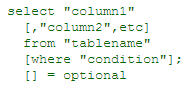
               SQL is the ‘Structured Query Language’ that is key for interacting with databases. [1] SQL is used to communicate with a database and relay specific commands. These commands can be used to update the information contained within the database, or draw certain information out. [2] The commands that are the life and blood of SQL are called ‘queries’. These queries start with a few basic functions, but when combined and expanded upon they become extremely comprehensive. A few of the most common commands accomplished with queries are: insert, select, create, etc… All databases start with a table and give the structure that queries need to work. Queries function based on codes, from simple to complex. A simple code would be to select a column within the desired table (as seen in Figure 1).
Figure 1. Sample Code for Selecting a Column
               This code could be expanded to include conditional statements in the where clause [1] to specify if the desired value is equal to, greater than, less than, etc. the referenced value. Once these skills have been mastered the same format can be used to create a new table, insert something into a table, manage records, or any number of things. The functions and code used to query within a database is the same platform of code used in other programs such as Matlab.

               SQL is important due to a number of reasons. One, it is one of the oldest programming languages. Many other programming languages have been modeled off of SQL and expanded upon. [3] Thus, it is not the easiest code to learn or use, because it seems almost primitive by today’s standards, but it is still incredibly useful. Likewise, due to SQL having so many other tools built off of it, it has almost become a universal language. SQLite is an SQL database that is used on Androids and IPhones, with some applications directly enabling its database. The universality of SQL creates the ability to code one program that will run on computers, phones, and anything else running SQL or SQLite. This type of interoperability is an idea fantasized by other software’s, like BIM.  Thus, the importance of SQL is its ability to transcend barriers and provide a platform to interact with almost any database

Citations
[3] http://sql.learncodethehardway.org/book/introduction.html

Comments

http://ae-510-ay15-16.blogspot.com/2016/02/b5-group-b-cummings.html
Comment to Bryan,

I agree that SQL is the platform upon which all websites have been built. This statement extends to the majority of programs, desktops, phones, and a full list of modern items. In relation to BIM, it is not surprising that SQL supplies the communication between the massive databases upon which programs like Revit run. The query command function allows the user to interact with different parts of Revit, including families. The family database is one of the most obvious databases within Revit. This database can be added to, selected from, and modified. Thus, I agree that SQL is a major part of BIM’s function, but I do not understand how it is a limiting factor. I believe BIM’s limiting factors come from other avenues.

http://ae-510-ay15-16.blogspot.com/2016/02/sql-stands-for-structured-query.html
Comment to Alex,

I like how you went into depth on how the queries work. The syntax is obviously important when coding a command for a database. If one comma, period, or letter is out of place the correct result will not come out of the query. This can make the process of querying complex and confusing to many people, which is why the user interface has been updated and reformatted in the programs built off of SQL. While these newer programs may be more user friendly, the importance of SQL has not faded. Without this initial language databases wouldn’t have made the progress they have made today.

Thursday, January 28, 2016

B4: Group B - Alex Palma


For my term project, I am working with Danielle Beynon and Dianna Vogel to create a Revit model of the Farnsworth House in Plano, Illinois. By making a Revit model incorporating all primary building systems, including architectural, structural, and mechanical, we can expand our knowledge in both Revit and BIM. All members of the group are of a structural concentration, and prior to this, we have only had significant experience with creating architectural models in Revit.

A short piece about the project topic itself; the Farnsworth House was designed by Mies van der Rohe. It was constructed in Plano, Illinois in 1951, as a weekend retreat for Edith Farnsworth, and has since changed ownership to the National Trust for Historic Preservation1. The structure is a simplistic design using steel framing elevated off the ground through extended columns, along with large glass panels for a lightweight façade and appearance. Van der Rohe attempted to make the structure appear as one large, uninterrupted piece, and as such, he attempts to keep consist structural member sizing throughout, even if over-designing. 

We have had the opportunity in class to read and discuss the concept of “Intelligent” building design, and as such, we chose a project that gives us the opportunity to use software based around this. Instead of simply drafting plans, elevations, and relevant documents in a drafting software such as AutoCAD, we can use Revit to model systems throughout the building and how they operate in conjunction with one another. For this project, my goal is to learn more about how to model mechanical systems in Revit and how Revit recognizes clashes and conflicts between separate systems, as well as resolution techniques for common clashes.

Outside of implementing the various systems into our model, our design will have to accommodate multiple components not stocked in the Revit libraries. Connections between members, such as the beam, column, or corner connections, all include components which are unique to the design and will need to be created for this instance. To do this, we will have to develop our knowledge of families in Revit, which we have learned in the past assignment, and use it to accurately model these components.

References:
1) http://farnsworthhouse.org/ 


Comments

Cathlene,
3D printed structural material is still coming along, so hopefully you'll be able to find enough research about it! I'd be interested in seeing, as you mentioned, the anisotropy of concrete formed in layers, and how significant the effect would be. I'm sure it would have to do with the type of concrete and more importantly the time between pouring layers, and there's probably research already done on this topic since it's integral to the structural performance.

Bryan,
Nice topic! A lot different than most of the other topics from the class. Using Matlab is likely a good choice for a project like this; I'd be interested in seeing how you model a sensor (or rather, sensor-like behavior) in Matlab. Depending on the parameters you establish, it might also be difficult to create a numerical or programmed "value" for these properties, so I really look forward to your end product.
 

B4: Group B - Dianna Vogel


I am working on a Revit project with Alex Palma and Danielle Beynon. Using Revit we plan to model the architectural, structural, and MEP systems of the Farnsworth House, and have them completely linked to each other. The Farnsworth House is located in Plano, Illinois and is currently owned by the National Trust for Historic Preservation. [1] It was originally built in 1951 by Mies Van der Rohe for Dr. Edith Farnsworth as a weekend retreat. Mies Van der Rohe strived for integration with nature, seen by the prominence of glass throughout the building (as seen in Figure 1). This structure was chosen by our group because it is the same house we are analyzing in our structural design class. Thus, we have all the structural and architectural documentation necessary to recreate an accurate model. It was chosen for our structural design class due to the beautiful minimalistic design.

Figure 1. Farnsworth House
Creating a model in Revit is, at its core, intelligent building design. Part of Professor Mitchell's definition for an intelligent building is ""Intelligence" requires the use of adaptive computer technology". [2] This leads right into the use of BIM, and more specifically Revit, to model a building. Revit becomes more adaptive each year with new abilities to customize the structure depending on the needs of the company or the specific project. This can be done by creating new families that may directly match what is trying to be created, compared to what Revit already offers. This allows companies to create their 3D model with unique structural, architectural, or interior components. Currently, my group members and I are trying to determine what families would be important to create for the Farnsworth house. One of the key components that Revit does not supply are the brackets that connect from the columns to the panes of glass (as seen in Figure 2). [3] These connections are too crucial to be left out of the model, thus it is beneficial that Revit can be customized to provide what we need.

Figure 2. Column Detail
There will be many challenges to face during our project. A main component is the incorporation of the three types of models (architectural, structural, and MEP) into one functioning system, with no clashes. Personally, I have seen the process done before during my co-op, but was only involved enough to learn how complicated the process can become. Furthermore, no one in our group has a background, or concentration, in MEP. Thus, it will be a very strong learning process to understand all the different components, how they interconnect, and how to model them in Revit. Finally, Professor Mitchell asked in class if we were planning on performing an energy analysis on the Farnsworth house. I have never done this before, so it would be very interesting, but I believe it will only be accomplished if we are successful with implementing the MEP model in a timely manner. I look forward to our project and increasing the depth of my Revit knowledge.


Citations
[3] http://www.loc.gov/pictures/item/il0990.sheet.00001a/

Comments
http://ae-510-ay15-16.blogspot.com/2016/01/as-i-haveprogressed-through-my.html?showComment=1454177551352#c6505760332188799298
Comment to James,
I really enjoy the outlook you have on your project. It is important to understand the concepts we use every day in our work. I am taking the same approach with my group’s project. I hope to understand the underlying concept behind using Revit to incorporate different types of models into one functioning unit. I look forward to hearing about what you and Bryan learn in your quest into sensors. This is an important concept for many of the environmental reasons you hit on. The pollution in certain areas of the world is getting to the point that sensors will need to become more advanced in order to detect and react the environment around them. The challenges you mentioned do include a lot of new concepts to learn, but they sound very interesting and will be useful down the road.

http://ae-510-ay15-16.blogspot.com/2016/01/b4-group-b-cummings.html
Comment to Bryan,
It is good to see that you and James have a stage process on how you are going to approach your project. It is important to perform a sensitivity analysis on the Matlab model when it is being created. Furthermore, all the uncertain parameters need to be established before the model is created, otherwise it may be unclear what the model is reacting to. The programming for the creation of an accurate model will not be simple and it is going to be very interesting how you tackle this task.


Tuesday, January 26, 2016

Group B: Question 2

BIM Improve Buildings vs. It will make no difference or degrade them

Possible degradation?
If people begin to rely on programs, such as Revit, for structural design or analysis without completing the necessary thought and hand calculations supporting the model. The resulting building could degrade or not have the structural strength necessary to withstand day-to-day use.

No Improvement?
The modeling process will be streamlined; however, it may not add any features to the building itself.

Improvement?

BIM could potentially improve the building if it is connected with 3D printing, thus more complex shapes could be created. Furthermore, BIM software could be used for energy analysis and the design improved.

Saturday, January 23, 2016

B3: Dianna Vogel - Group B

This post is about the current problems people face with Revit/BIM. Resulting from the introduction to the depth of Bentley software in class last week, the focus is generally going to be centered on the capabilities and advances that Revit currently lacks.

A key issue that many people have hit with Revit, and eventually turns them to Bentley, is the limited size of the model that Revit can handle. This occurs with mid-rise buildings, around 100,000 sq. ft. and when more than five people are attempting to collaborate on one model. [1] These numbers make sense; personally I have never known Revit to be used for more than a 2-3 story building. On my last co-op, at an engineering design firm, Revit was mainly utilized for the Patco stations that were being redesigned. These were not overly large stations by any means, so Revit had no problem. However, it is understandable that Revit would begin to have issues as the file became larger, because all the information is stored on one database. However, Bentley enables the use of many databases, so the information storage capacity almost seems limitless. This allows massive projects, such as re-creating an entire city, to be modeled within Bentley products.

Last week the topic of interoperability was researched. This is a function that is necessary in all BIM products. As mentioned before, on my last co-op I helped with the Revit drawings for the redesign of Patco stations. Before then I did not know that Revit had more than just architectural models. Suddenly I was trying to deal with an architectural model linked to a structural model, linked again to a MEP model. This became very confusing. I want to be able to master this skill, which is why my team’s term project is to create a fully outfitted house (architectural, structural, and MEP) within Revit. However, shouldn’t it be easier? As Professor Mitchell mentioned in class, Revit has its reasons for doing this. All disciplines care about different dimensions and portions of the model. However, it would still be much simpler for everyone if all the systems were in one drawing, and you didn’t have to wait until the end to see what conflicts may exist between plumbing and structural drawings. [2]

A problem for Revit and many BIM systems is the functionality with the construction world. Firstly, many clients prefer different systems. [3] Therefore, it is very difficult for companies to make a final decision on what system to implement. This is where a common drawing format, such as IFC, should be adopted by all packages. This would allow companies to pick the system that best fits their needs, and not worry about the format the client will need. Currently, Revit is used as a way to visualize how all the building will look in the future. It would be very useful if detail drawings or shop drawings could be pulled directly off the model for the designer to give to the contractor, client, etc.     
 
Thus, Revit and BIM still have a long way to go before they are perfect.

Sources:
[3] http://www.augiuk.co.uk/index.php/articles/17-articles/31-the-problem-with-revit

Comments:

Comment to Bryan Cummings,

I used Tekla during my last co-op as well. I agree that it can be both helpful and frustrating in the same breath. Tekla was used by the contractors to model the building, but very rarely were the information fields for the individual parts filled out. I believe this stems from companies seeing the usefulness of BIM, so they want to use it. However, these companies do not fully commit to using BIM and continue a complicated half and half lifestyle. If they were to harness BIM at its full capacity, it would be difficult at the beginning to transfer everything over, but the end product would be very beneficial. Unfortunately, many companies are not willing to put in this initial investment of time, so the incorporation process is a slow one.

Comment to Alex Palma,
I agree with the point you made about the disadvantage of the training time that goes into implementing a 3D modeling BIM program, such as Revit, into a company. Many managers struggle with the decision on whether or not to pull employees off projects to dedicate up to a week of training to a new system. Obviously, the end result would be very beneficial; however, when a company is trying to meet week-by-week deadlines it becomes hard to let the employees go. Thus, the training generally comes in stages, with each individual employee completing the training once they have a free week. While this helps the company keep on schedule, it delays the full implementation of the hardware for the company. Thus, the decision to adopt a BIM program, or upgrade, generally comes with a great deal of frustration.
 

Friday, January 15, 2016

B2: Dianna Vogel - Interoperability

               Interoperability represents the ability to exchange data between different applications, which allows different fields of experts on separate applications to contribute to a project. It is important to have interoperability when so many different types of people (i.e. architectural, structural, MEP) are all trying to work on the same building. In this post the focus will be on the progression and use of the Industry Foundation Classes (IFC) data model. This is one of the major data models in use today, and a main focus of chapter three (Interoperability).
               First, a little background on how IFC was started; in the mid-1980’s a technical committee was initiated to determine a better way to exchange data between systems. The organization was STEP (Standard for the Exchange of Product Model Data), and their main product was the creation of the EXPRESS language. EXPRESS is a language that has an object reference a computer language that represents more than one physical object; it can represent ‘conceptual or abstracted objects, materials, geometry, assemblies’, and more. [1] IFC uses ISO-STEP technology (i.e. EXPRESS) to exchange consistent data representations of building information among software applications. [1] The IFC is supported by BuildingSMART (previously International Alliance for Interoperability (IAI)), which was created to support integrated application development.


Figure 1. System Architecture of IFC Subschemas
               Figure 1 depicts a very clear representation of how the objects, or entities, are configured in IFC. The top level represents the domain specific paths, and the base entities (bottom layer) represent general building elements. The base-entities can be specialized into sub-entities, due to IFC being object-oriented and an extensible data model. The IFC covers basic geometry, including extruded shapes, Bezier surfaces, and now Non-Uniform Rational B-spline (NURBS). However, it cannot handle complex, editable parametric models currently (at the time of this books publishing); however, translators are being written to correct this. IFC data models can relate any sort of classification, such as: decomposes (between assemblies and their parts), connects (topographical relationships), and more. Property sets can be assigned to different material behaviors (i.e. thermal materials and mechanical properties) and properties relating to costs and time. One of the newest and most impressive property sets that can be applied is the reinforcement in concrete. This information is very useful when trying to analyze how the building will operate under different loads. However, properties dealing with tolerance and uncertainty are still lacking.
               IFC data models are used and shared by using P-21 translators, both for export and import. Currently, IFC Model Views are being developed to assist in the ease and precision of exchanging information between different parts of a project (i.e. the designer and structural engineer). The IFC data model is continuously evolving, with a new release every two- years. The main downside to this model is the massive level of expansion, and minimal support. However, due to the age of this book there have most likely been a variety improvements over the years. Currently, there is a variety of BIM software that has IFC export available, ArchiCAD, Autodesk ADT, Tekla Structures, and more. [2]
 
Sources
[1] Eastman, Charles M. BIM Handbook: A Guide to Building Information Modeling for Owners, Managers, Designers, Engineers, and Contractors. Hoboken, N.J: Wiley, 2011. Web.

[2] "About BIM and the IFC." Solibri, 2016. Web. 15 Jan. 2016.

Comments
[1] http://ae-510-ay15-16.blogspot.com/2016/01/b2-group-b-cummings.html
Comment to Bryan Cummings,

I agree that understanding the limitations on interoperability systems is important within all types of software. Especially, in construction where the designers, engineers, and contractors have to work so closely together on the same model/system. As discussed in class, the construction field is typically 10 years behind the aerospace field technologically, due to funding disadvantages. This is also seen in interoperability, in the aerospace field one computer system is used by all subsets in order to create a working system. Thus, the technology is out there; the construction field just has to put forth the time, effort, and funding to have the payoff of a fully integrated system.


[2] http://ae-510-ay15-16.blogspot.com/2016/01/b2-group-b-alex-palma.html
Comment to Alex Palma,
You focused on a different part of the chapter than I did; however, I enjoyed the information you pointed out. I have never personally used ProjectWise at either of my Co-op’s, but its ability to manage so many of files at one time seems extremely useful. Nevertheless, interoperability is an extremely important factor when it comes to file share systems. Hopefully ProjectWise can evolve into a system that can allow multiple users to make changes at the same time (possibly through a cloud-like server as you mentioned), because that is what is necessary in the construction field today. In the future, the same concept of multiple people working on a Google Drive document could be incorporated in to a BIM system. Obviously, BIM systems are much more complex, but that is what the technology is moving towards.
 

Friday, January 8, 2016

B2: Future - Dianna Vogel


              This post discusses the progress and intertwining of BIM, 3D printing, structures, and the overall future of all these topics. None too surprising, the future of all these topics come together into something straight out of a science-fiction novel.
3D printing is the process of multiple layers of a material being laid upon each other, in small amounts, until an object is formed. Many materials can now be used to complete this process, including: plastics, rubbers, and even metals. The field of metal 3D printing is new and still growing, with one viable method being direct metal laser sintering (DMLS). This technique spreads metal powder across a build platform and is then melted, which is slightly different than the extrusion process of general 3D printing. The future of 3D printing is the increased use of more useful materials (i.e. metals) and finding even stronger materials, such as graphene, to incorporate into all fields.
              Building Information Modeling (BIM) becomes more used in companies every year. However, the problem in the current years has been how to incorporate 3D modeling programs, such as Revit, with 3D printing. Full integration is still an area of ongoing research and development, generally Autodesk’s 3ds Max is currently used to bridge the gap. The concept is tantalizing, especially once a house was built by Danish architects Frederik Agdrup and Nicholas Bjorndal using only a computer, a printer, and plywood. The 3D model was transformed into a manufactured template which was sent to the printer, a computerized milling machine (CNC machined). The benefit of using this type of technology was clear: little waste from the CNC-machine, no concrete was used, wood and glass were the only wall materials used, and the structure only interfaces with the ground at its screw pile foundations. This creates a structure with minimal environmental impact.
              An even more recent example of 3D printing’s incorporation with structures is currently occurring in Amsterdam. MX3D (the company heading the project) has the ambitious goal of building a bridge over a canal in the center of the city, with only a 3D printer. This 3D printer has some revolutionary new tricks though, including a welder that has the ability to “draw” fast-setting metal structures (the MX3D-Metal). The bridge will be printed out of steel by welding small increments of molten metal to the structure, resulting in lines of steel. This project is definitely revolutionary in the field of 3D printing structures.
              The future of using BIM modeling, and then 3D printing in order to create structures is endless. With 3D modeling shapes do not have to be rectilinear, as generally seen in construction. With 3D printing curvilinear shapes, similar to eggs, can be created. These shapes are stronger and less material can be used to create them. Along this same line of thinking, hollow shapes can be created for buildings that would leave room for utilities. The most futuristic line of thinking for this technology is the use of 3D modeling and printing for future colonization on Mars; it would be the ideal set-up. Robots could be sent to the surface before human space-crafts arrive, and they could have the structures built before the craft even touches down.
 Sources:
[5] http://www.viatechnik.com/3d-printing-and-looming-changes-in-the-construction-industry/

Comments:

[1] http://ae-510-ay15-16.blogspot.com/2016/01/group-b-week-2-bryan-cummings.html
Bryan,
We studied a couple of the same articles, so I enjoyed your point of view on the topics. However, I did not see the article about the ‘Bloom’ structure created by the research team at Berkeley. I do believe that their method, where the dry cement powder is laid for each layer first and then sprayed with water to harden, is the more precise method. This would work really well to build complex cement structures, especially if the 3D printing machine is mobile. Furthermore, I saw that you also read the article about the future 3D printed steel bridge in Amsterdam. It is fascinating how the 3D printing machine will build its own supports as its builds the bridge. This technology will be revolutionary in the field of construction, especially with the atrocious shape some bridges are in around the United States. Finally, I did not see the research in creating a cement like substance, using the local material on the moon, for 3D printing structures. I will look forward to looking at the final design for the structures, in order to see how they will take in to account all the risks from the atmosphere.

[2] http://ae-510-ay15-16.blogspot.com/2016/01/b1-group-b-alex-palma.html?showComment=1452465323644#c7056173898726598249
Alex,
You chose very different articles than I did, which makes reading your post very interesting. I particularly liked the section on the BIM software AECOism. I have never heard of this software, and with all the integration properties I agree it sounds like a very powerful tool. I am curious if it will become a major competitor of Revit shortly. This would be especially true if AECOism was able to adapt to the 3D printing craze faster than Revit has been able to, thus far. Furthermore, you uncovered another 3D printer benefit that I had not heard of before, the ability to adjust in areas of high and low stress concentrations in order to save material. This would be very useful in a building, as long as the appropriate variety of load calculations were done before hand. Truthfully, in the future BIM type software will most likely be able to take an inputted design and parameters, and then automatically determine area that could use less, or more, material.

Tuesday, January 5, 2016

Group B Discussion Post - Week 1

After watching the videos, we can see 3 main changes. The first is an increase in speed in the drone's movement, and a more fluid travel throughout it's path. The second was a better coordination between the drones, as often times, both drones were working to create the same section, and interacting with one another to create sections. Thirdly, the drones had the ability to work in a changing environment; unlike the first, where the structure is more stable, the drones were able to work with a swaying rope which did not always have a defined position.

These tools may be applied in the future in more unknown or unsafe environments, where human interaction is more difficult. The increase in speed makes the use of drones more applicable than before.

Dianna Vogel Introduction

My name is Dianna Vogel. I am a Junior Civil Engineering BS/MS student (structural concentration) with a minor in Engineering Management. I am interested in taking AE-510 in order to gain some database knowledge, further explore BIM, and discover what the umbrella of Intelligent Buildings encompasses. I expect at the end of this course to be able to sufficiently manage a database and explain knowledgeably the definition of an Intelligent Building. With my current understanding, an Intelligent Building is one that responds to its environment in such a way that solves a problem faced in the surrounding area or culture.

Thursday, December 31, 2015